From 3D dyke design to flawless execution
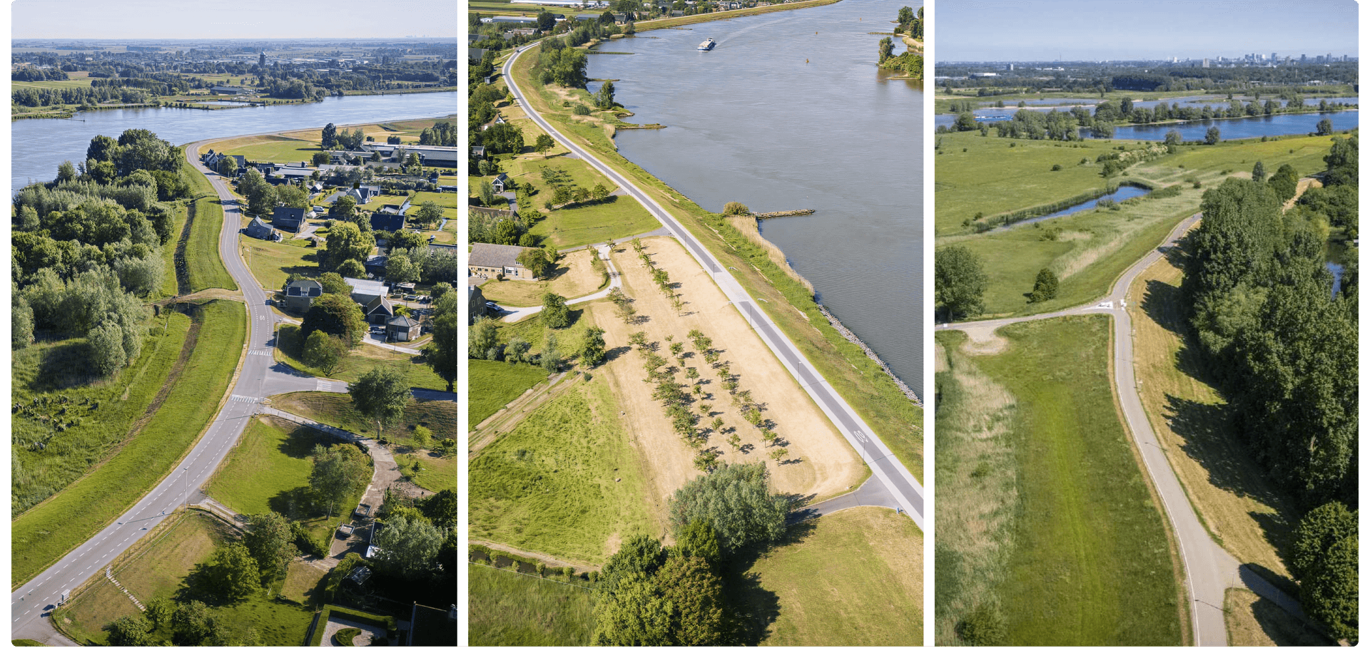
Forty kilometres of dyke, three contractors, one shared objective: reinforcing the southern bank of the Lekdijk for generations to come. For the SAFE Dyke Alliance, the project is defined by precision, from the initial 3D design through to the file read by the construction machine on the dyke.
Context
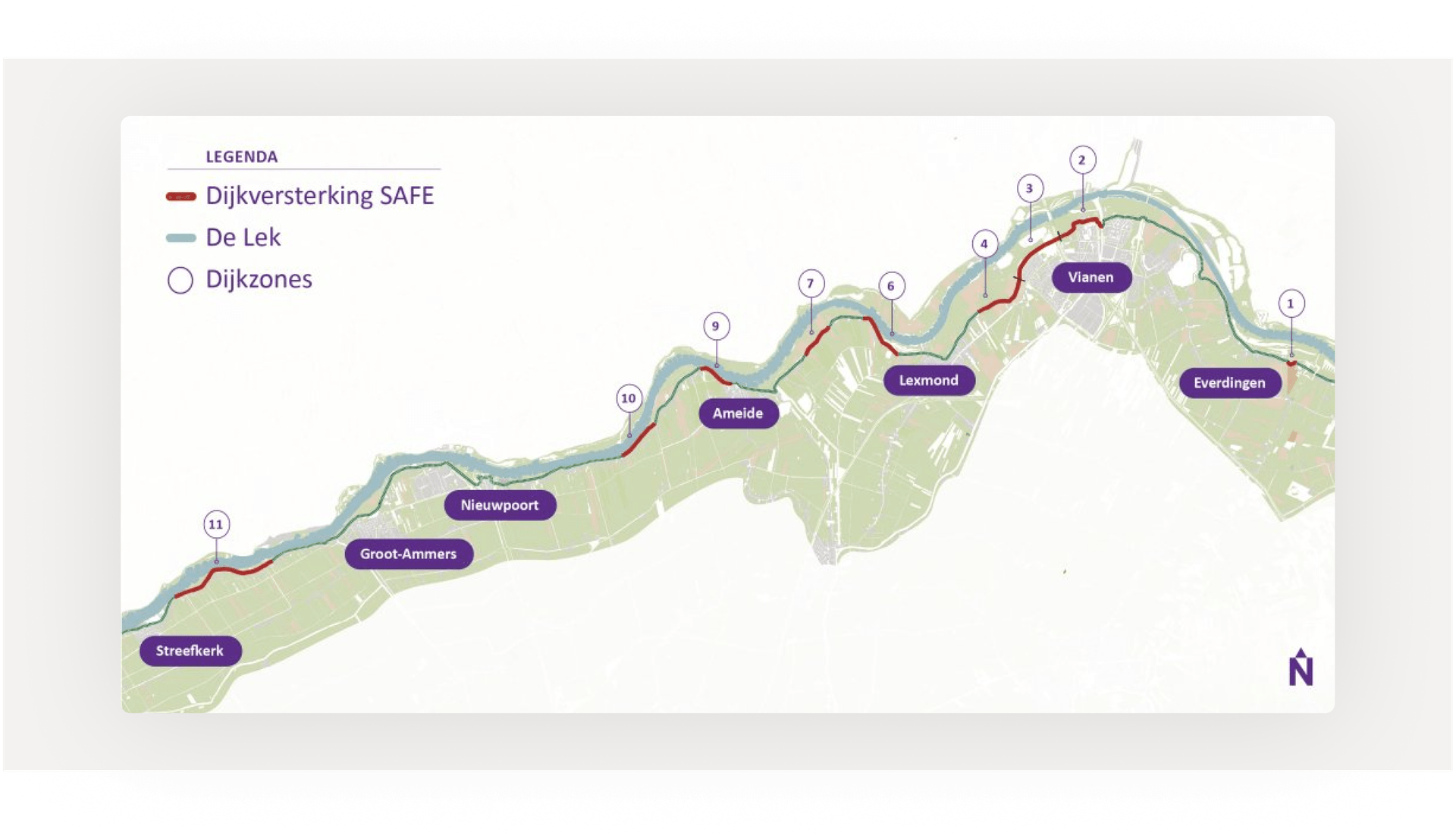
On behalf of Waterschap Rivierenland, the SAFE Dyke Alliance, a joint venture between GMB, Ploegam and Dura Vermeer, is carrying out the reinforcement of the southern bank of the Lekdijk. The Streefkerk–Ameide–Fort Everdingen stretch covers 40 kilometres, of which 12 kilometres are being reinforced. The project forms part of the national Flood Protection Programme and contributes to the protection of the Alblasserwaard and Vijfheerenlanden regions.
The project combines high technical precision with operational complexity: three contractors, multiple disciplines, continuous iterations between design and execution, and stringent requirements from the water authority regarding layer thicknesses, gradients and model accuracy.
Operational challenge
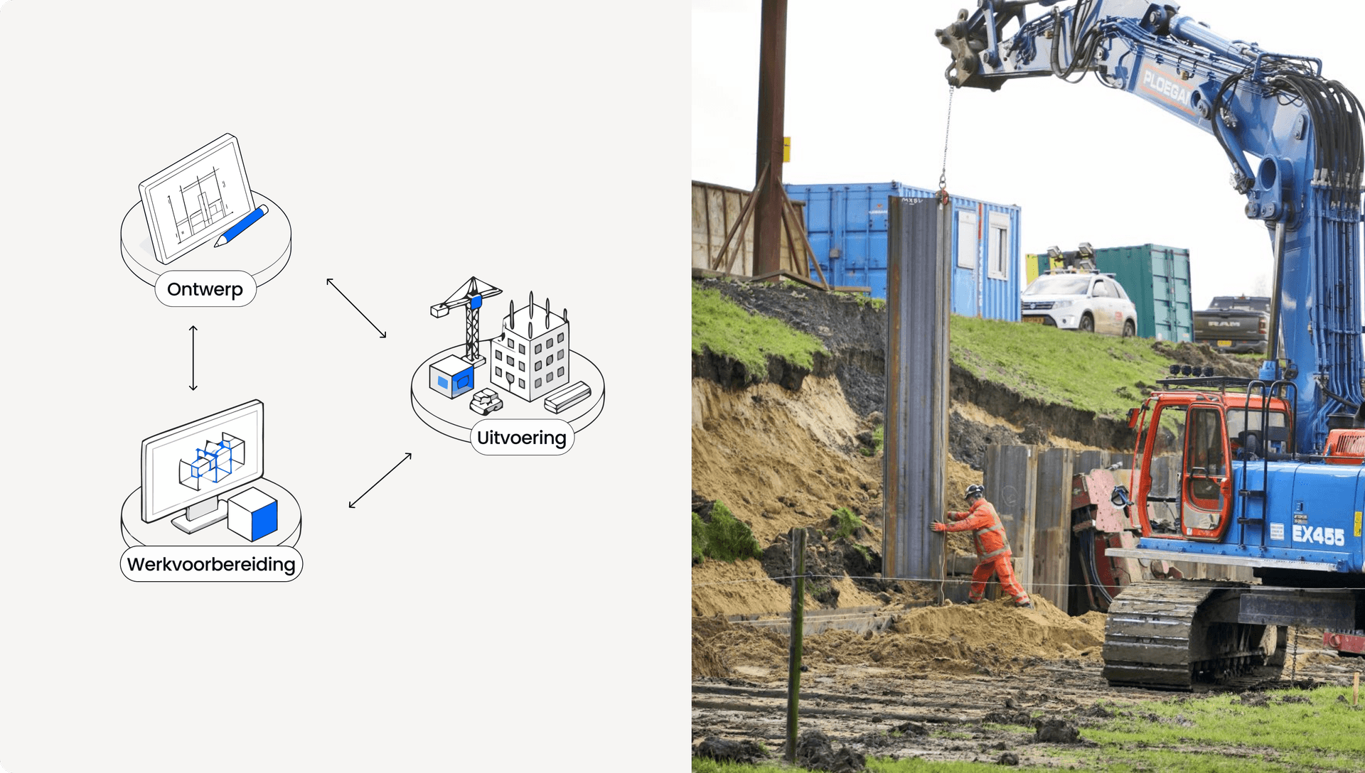
Each dyke section is elaborated in a detailed 3D model. From that model, successive simplified versions are produced until a stripped-down version is suitable for direct machine processing on the dyke. Every change to the base model required manual propagation across all derived versions, an error-prone process in which versions frequently fell out of synchronisation.
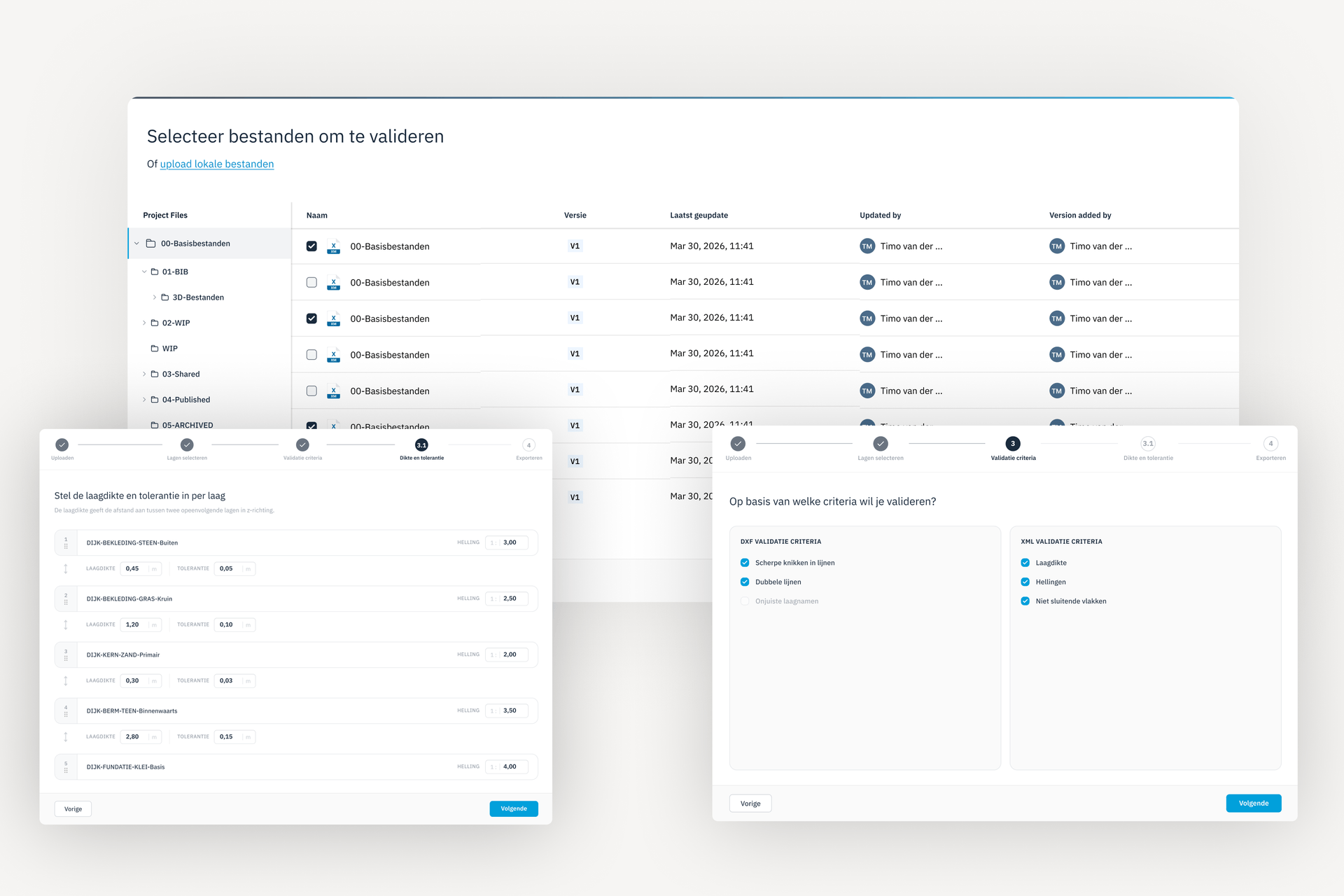
In addition, each model had to meet specific requirements set by Waterschap Rivierenland: prescribed layer thicknesses for asphalt, clay and sand; maximum gradients on slopes; surface integrity. During two workshops, six recurring error patterns were identified that are practically impossible to verify consistently by hand: deviating layer thicknesses, excessively steep gradients, unnatural kinks in lines, gaps in surfaces, incorrectly labelled components, and duplicate lines.
On the execution side, the survey process was equally manual. The site surveyor compared measurement results against design tolerances in Excel and reported deviations to the water authority, a time-consuming and error-prone process that offered no real-time visibility.
Where value was being lost
The critical break occurred between designer and execution. Models were validated late in the process, only on the final machine file, not during the design phase. Errors that could have been caught earlier were reaching the construction site. The consequences are directly operational: a single error in a machine file brings the site to a standstill. On a 40-kilometre project, those failure costs accumulate rapidly.
Studio Vi’s approach
The full operational process was mapped end to end, from designer to site surveyor. Validation criteria were distilled from the water authority’s requirements and the recurring error patterns identified during the workshops. On that basis, the team determined which validations could be automated and what the logical sequencing of the solution should be.
The platform integrates with the team’s existing working environment, no additional account management, no new systems alongside existing workflows. The architecture is modular, allowing new validation criteria, additional disciplines or extensions to be added without disrupting the existing structure.
Modules
Model Validation The designer uploads a model and receives an overview showing only the deviations. The module automatically checks against the agreed criteria: layer thicknesses, gradients, surface integrity, label consistency and duplicate geometry. Validations can be run on final machine models as well as during the design phase, so that errors are intercepted early in the chain.
Survey Validation Automated processing of survey data: checking for duplicates, cleaning raw data and comparing against design tolerances. Automations the team had developed independently have been integrated and extended. Reporting to the water authority is based on validated data, not manual checks.
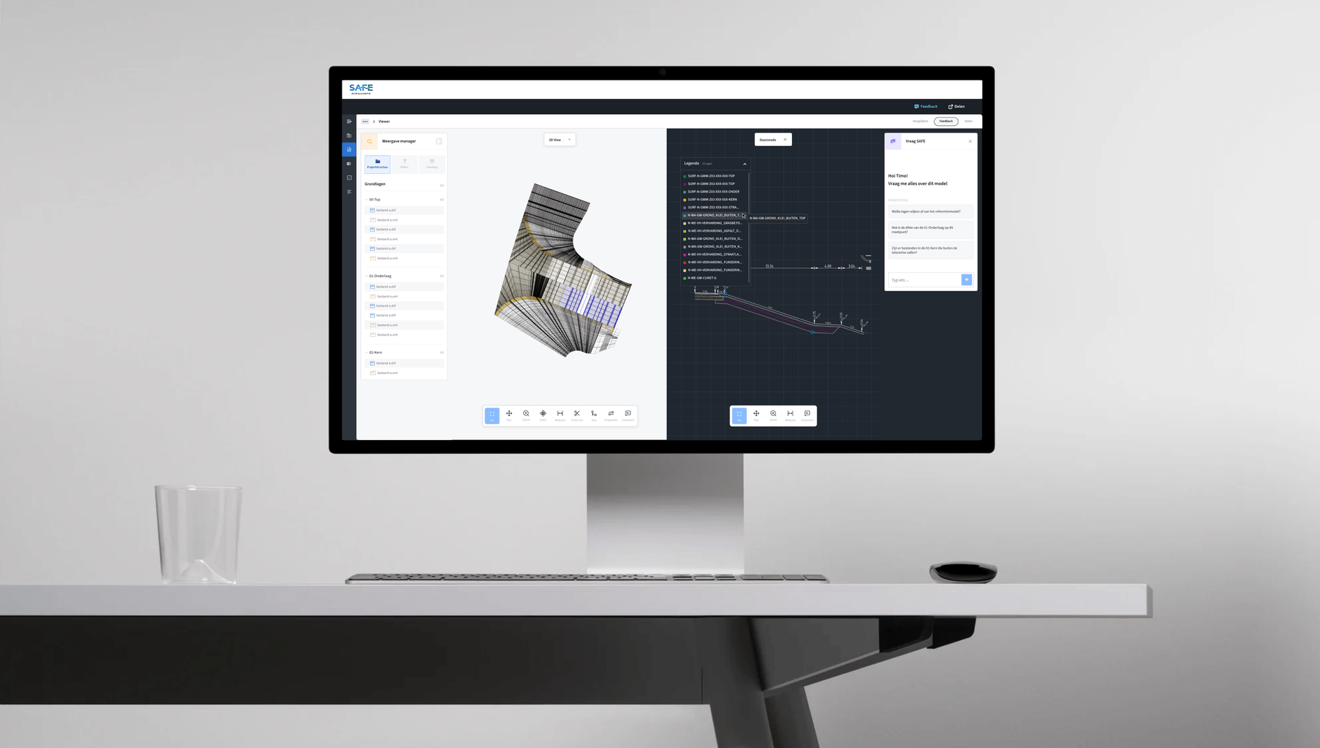
Collaboration Viewer A web portal in which the designer and site surveyor work simultaneously on a model, without requiring heavy design software to run locally. Models open directly in the browser. Both disciplines can place comments on specific points within the model, run validations and check tolerances from a single shared environment.
Connected operations
Designers and site surveyors work from one shared environment rather than isolated files, email exchanges and parallel Excel checks. Validation takes place during the design process, not only on the final model. Errors become visible before they affect execution. The communication line between disciplines is direct, traceable and embedded in the working process.
Operational impact
The SAFE platform forms a digital bridge between design and execution for a 40-kilometre dyke reinforcement project involving three collaborating contractors. Designers receive feedback more quickly and reliably. Site surveyors validate more efficiently. Models that reach the machines have been verified against the criteria that matter operationally.
The risk of delays caused by model errors has been structurally reduced. Iterations between disciplines proceed faster. The platform provides the foundation for subsequent modules, including the digital earthworks balance and scenario analyses for ground movement in conjunction with project phasing.